
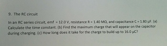
In an RC series circuit emf 12.0 v, the interplay between electromotive force (EMF) and circuit resistance governs the flow of electrical current. This intricate relationship profoundly influences the charging and discharging behavior of capacitors, the voltage distribution across circuit elements, and the circuit’s practical applications.
Delving into this captivating topic, we embark on a journey to unravel the complexities of RC series circuits and the pivotal role of EMF within them.
As EMF drives current through the circuit, the interplay between resistance and capacitance shapes the dynamics of capacitor charging and discharging. Understanding these processes is crucial for harnessing the full potential of RC circuits in various applications.
RC Series Circuit
An RC series circuit consists of a resistor (R) and a capacitor (C) connected in series. When an electromotive force (EMF) is applied across the circuit, it causes a flow of current through the resistor and the capacitor.
EMF and Circuit Resistance

The EMF (electromotive force) of a circuit is the voltage applied across the circuit. It is the driving force that causes the current to flow through the circuit.
The circuit resistance (R) is the total resistance of the circuit, which includes the resistance of the resistor and the capacitor.
The relationship between EMF, circuit resistance, and current is given by Ohm’s law:
I = EMF / R
where:
- I is the current flowing through the circuit
- EMF is the electromotive force applied across the circuit
- R is the circuit resistance
Capacitor Charging and Discharging
When an EMF is applied across an RC series circuit, the capacitor starts to charge. The charging process involves the accumulation of charge on the capacitor plates.
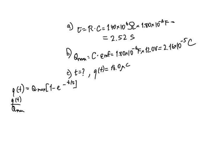
The rate at which the capacitor charges is determined by the time constant of the circuit, which is given by:
τ = RC
where:
- τ is the time constant
- R is the circuit resistance
- C is the capacitance of the capacitor
The capacitor continues to charge until it reaches its maximum charge, which is equal to the EMF applied across the circuit.
When the EMF is removed from the circuit, the capacitor starts to discharge. The discharging process involves the release of charge from the capacitor plates.
The rate at which the capacitor discharges is also determined by the time constant of the circuit.
Resistor and Capacitor Voltage
The voltage across the resistor and the capacitor in an RC series circuit is not constant.
During charging, the voltage across the resistor is initially high and gradually decreases as the capacitor charges.
During discharging, the voltage across the capacitor is initially high and gradually decreases as the capacitor discharges.
The voltage distribution across the resistor and capacitor is given by:
VR= EMF
- (1
- e -t/τ)
VC= EMF
e-t/τ
where:
- V Ris the voltage across the resistor
- V Cis the voltage across the capacitor
- EMF is the electromotive force applied across the circuit
- t is the time
- τ is the time constant
RC Circuit Applications
RC series circuits have a wide range of applications, including:
- Filtering:RC circuits can be used to filter out unwanted frequencies from a signal.
- Timing:RC circuits can be used to create timing circuits, such as those used in digital clocks.
- Energy storage:RC circuits can be used to store energy in the form of a charged capacitor.
- Coupling:RC circuits can be used to couple two circuits together, allowing signals to pass from one circuit to another.
The EMF applied across an RC circuit plays a crucial role in determining the performance of the circuit.
For example, in a filtering application, the EMF determines the cutoff frequency of the filter.
In a timing application, the EMF determines the time constant of the circuit, which in turn determines the timing interval.
FAQ Guide: In An Rc Series Circuit Emf 12.0 V
What is the relationship between EMF and current in an RC series circuit?
EMF is directly proportional to the current flowing through the circuit, as per Ohm’s law: EMF = I – R.
How does EMF affect capacitor charging time?
Higher EMF leads to a faster charging rate, reducing the time constant for capacitor charging.
What factors influence the voltage distribution in an RC series circuit?
EMF, resistance, and capacitance determine the voltage distribution across the resistor and capacitor.

